
Overview
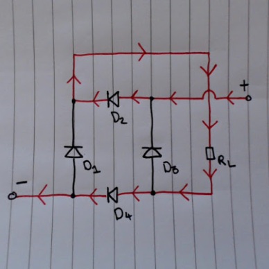
This is a diode bridge. It converts alternating current (AC), into direct current (DC). The circuit is set up so that current is always flowing towards the input of RL, and away from the output. More information about the properties of diode can be found here:’https://tphelectronics.com/2015/09/29/diodes/‘

AC signal output is most commonly just connect to ground (0v).
RL represents the circuit to which you’re applying the DC voltage.
Signal diagram explanation

This shows one full oscillation of the AC signal at the input. Whilst the signal is above the horizontal line, the voltage at the signal input is positive. Whilst the signal is below the horizontal line, the signal input is positive
Flow of current during positive half of the oscillation.

During the section labelled ‘Input is positive’, here’s how the current flows around the circuit:

The reason why the current can’t flow through D4, after passing through RL, is because D4 has already been reverse biased by current flowing from the AC input.
Flow of current during negative half of the oscillation.

During the section labelled ‘Input is negative’, here’s how the current flows around the circuit:
Conclusion.
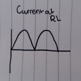
As you can see, regardless of whether the AC input is positive or negative, the current flowing through RL never changes. If we could see what the current looked like at RL, It’d look something like this:
Notes for future.
I’ll add in a diagram and explanation as to how to dampen the rippling effect seen in the graph above.

Might want to throw some capacitance across the output to tame the ripple in current.
LikeLike
I randomly threw this post up here with just the image last night. I don’t know why it’s gotten so much attention since then :’)
But yes, I’m going to add another diagram with a capacitor across the inputs, to act as a reservoir and text explaining it. You are 100% correct, and I’ll get to that soon.
LikeLike
What size capacitor would you use with a +-5v AC input?
LikeLike
Use this formula: Vripple = Iload / 2 f C
LikeLiked by 1 person
I think it doesn’t work
Input should be fed in at one diagonal and output should be drawn at other diagonal
To know more amazing innovative things on electronics visit https://theelectronicline.wordpress.com
LikeLike
I double checked using multiple sources, and this is correct. So yes, it should work.
LikeLike
How it works
LikeLike
During positive cycle it passes though diode bw input and output
LikeLike
It’s not working I’ve checked it
LikeLike
I hope that this post is clear and works for you now.
LikeLike
Yes bro this works, but the previous doesn’t
LikeLiked by 1 person
This diagram is really unclear and confusing. Let me update it first.
LikeLike
Where are you from?
LikeLike
England. What about you?
LikeLike
India
LikeLike
Nice, which part of India?
LikeLike
South India
LikeLike
Telangana state
LikeLike
From which university r u from?
LikeLike
It really annoys me that you can’t reply to a reply on here. I’m not currently in university, but I’m applying at the moment. I want to do electronics and communications engineering at kent university, if you’re interested.
Are you currently studying at university?
LikeLike
I have completed my engineering
LikeLike
Pingback: Diodes | TPHelectronics