A difference amplifier has two inputs. It compares them both, and then cancels out any similarities between them. Once any common voltages have been cancelled out, the differences are amplified.
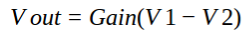

A difference amplifier has two inputs. It compares them both, and then cancels out any similarities between them. Once any common voltages have been cancelled out, the differences are amplified.
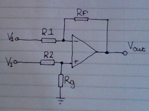
A comparator is one of the simplest op amp subsystems. It simply compares two voltages, and the output either goes high or low depending on which input is the higher voltage.
Generally, one of the inputs is fixed to a set voltage (a reference voltage), whilst the other varies depending on an analogue input. Here’s an example:
Using a potential divider calculation, the voltage at the non-inverting input can be calculated as 3v. Because of this, when the voltage at Vin is above 3v, the output will be low. When the Voltage at Vin drops below 3v, the output will be high.
A Schmitt trigger has one input and one output. It sets the output to one of two states depending on the voltage at Vin. Because of the nature of inverting op amp set-ups, the outputted signal will be inverted. When Vin goes below a certain voltage (the lower switching threshold), Vout goes high. When Vin goes above a certain voltage (the higher switching threshold), Vout goes low.

Because Schmitt triggers have an upper and lower switching threshold, they’re much better at cleaning up noisy signals than a single switching threshold. This is because with a single threshold, the noisy signal will jitter between each side of the threshold, causing it to trigger multiple times.
A potential divider reduces the voltage in a circuit. If R1 and R2 are equal, the voltage at Vout will be half of that at Vin.

Here is a condensed equation to calculate the voltage at Vout:
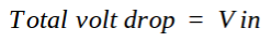
This can also be calculated by finding the current that flows through the potential divider. To do this you find the total volt drop and divide it by the total resistance (because the voltage drops to 0, the total volt drop is equal to Vin).
![]()

After the current has been found, Vout can be calculated my multiplying R2 by the current(i) (you use R2, because this calculation finds the volt drop across the resistor, so Vin – volt drop across R1 = volt drop across R2 = Vout).

A Non-inverting amplifier increases the amplitude of a signal. Its input resistance is that of the op amp itself (infinite in an ideal op amp), which makes it perfect for amplifying small signals, that can provide very little current on their own.
One thing to note quickly. The output can never be higher than the positive supply voltage, or lower than the negative supply voltage.

Non-inverting amplifiers however, can only provide a minimum gain of one. This means the output will always be at least the same value as the voltage on Vin. Its gain can be calculated by using the following formula:
An inverting amplifier increases the amplitude of a signal. But due to the fact that the signal is fed into the inverting input, the output signal will be inverted. However, unlike Non-inverting amplifiers, they can have a gain of less than one.
One thing to note quickly. The output can never be higher than the positive supply voltage, or lower than the negative supply voltage. This means that for an inverting amplifier to work you need the negative supply pin to have a voltage below ground (e.g -6v).

In inverting amplifiers, the gain can be calculated by dividing Vout by Vin. In addition to this, the same figure can also be acquired by dividing the feedback resistance by the input resistance ( feedback resistance = Rf, Input resistance = R1) . However, because the output is inverted, the value of the feedback resistance needs to be inverted too. From all of this, we can deduce the following equations:

If two inverting amplifiers are used in series, the inversion can be rectified. A schematic and equation is shown below to demonstrate this.
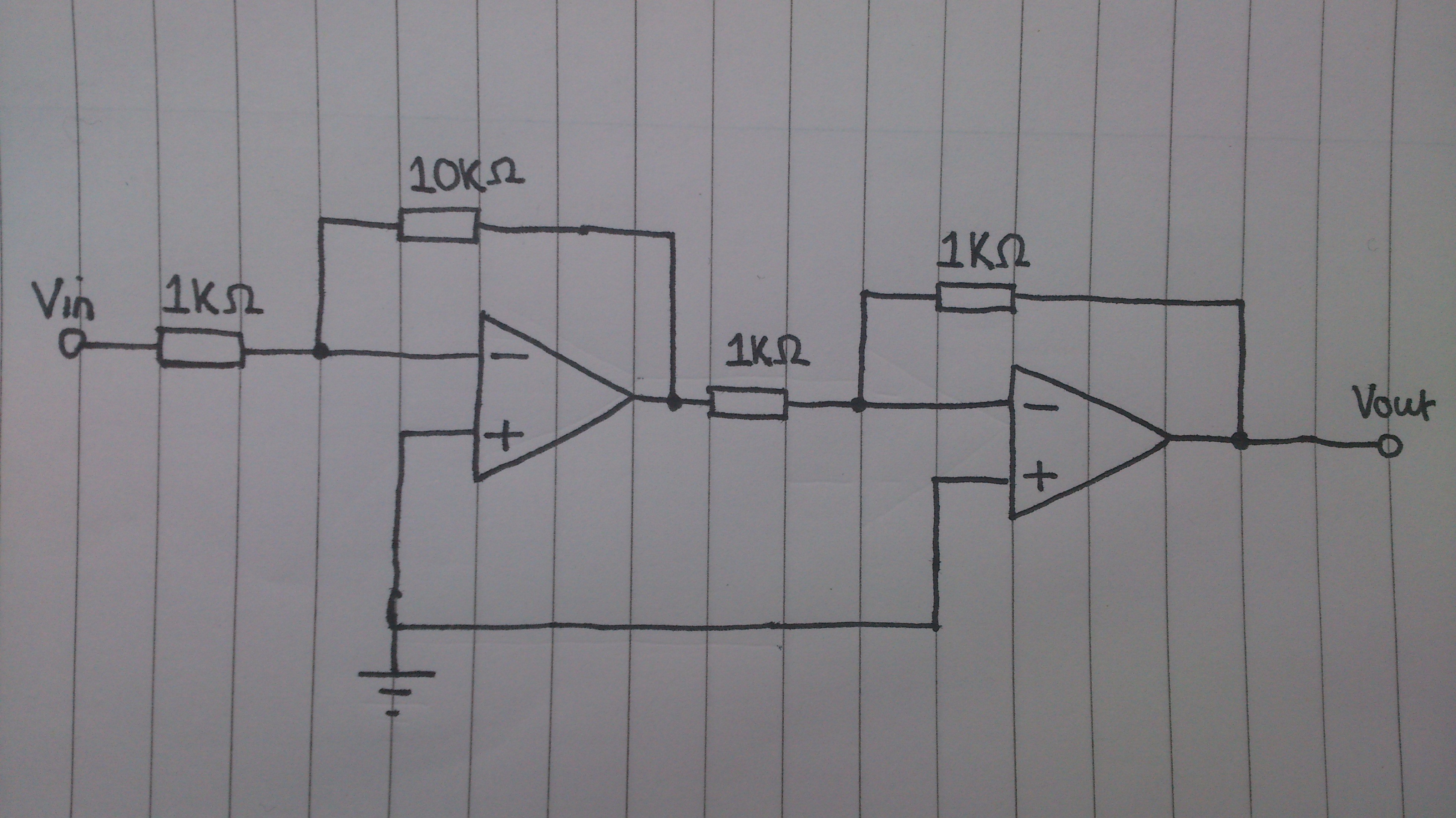
The gain of the first op amp is calculated:
![]()
Then the gain of the second op amp:

Now assuming that Vin = 0.5v, the output of the first op amp would be the following:

Finally, with -5v being inputted into the second op amp, the output will be once again positive:

Therefore the total gain of the circuit is 10, meaning that the inversion has been rectified.
‘Passive’ refers to the fact that this type of filter is incapable of power gain and uses no active components. This also means that no external power source is needed for it to function.

A low-pass filter, as the name suggests, allows low frequencies to pass whilst cutting off higher frequencies. The cut-off frequency (Fc), is calculated by using the formula below. ‘R’ is the resistor value, and ‘C’ is the capacitor value.

‘Passive’ refers to the fact that this type of filter is incapable of power gain and uses no active components. This also means that no external power source is needed for it to function.

A high-pass filter, as the name suggests, allows high frequencies to pass whilst cutting off lower frequencies. The cut-off frequency (Fc), is calculated by using the formula below. ‘R’ is the resistor value, and ‘C’ is the capacitor value.

The XNOR gate is an inverted XOR gate. The out put is only true when either all the inputs are false, or all the inputs are true. It is effectively an XOR gate in series with a NOT gate.


A NOR gate simply produces a true output only when all of the inputs are false. It is effectively just an OR gate in series with a NOT gate.


