Potentiometers

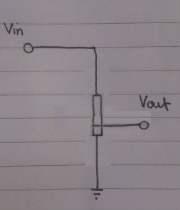
Potentiometers are essentially potential dividers with one significant difference. You can variate the voltage that is being outputted. The resistance, and consequently the voltage, can be changed by adjusting the position of the knob. For reference, here’s the link to the post on potential dividers:  ‘https://thelectronicsblog.wordpress.com/2015/11/11/potential-dividers’


potentiometer real view

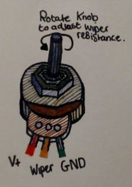
Above is a diagram of what a potentiometer physically looks like. Rotating the knob directly changes the position of the wiper. The position that the wiper is in dictates the voltage outputted from the wiper wire.

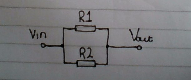
To explain this more easily, imagine that the two resistors from the potential divider diagram have been squished together, and the insulated coating has been removed.

potential-divider1potential-divider pot.jpg

Assume that R1 and R2 in the diagram on the left are each 5k. They have been squished together on the diagram on the right. This forms a 10k piece of resistive material . But because the position of the Vout wire is approximately half way down, it is the same as having a 5k resistors on each side.

potential-divider pot 2

Now assume that the Vout wire is instead now 3/4 of the way down the resistive material. This is equivalent to having a 7.5k resistor as R1, and a 2.5k resistor as R2.

Now that the premise behind potentiometers has been explained, here’s the original physical diagram shown side by side with what the internal wiring of a potentiometer would actually look like:
pot1potentiometer real view


Hopefully you now understand how a potentiometer works. However, if you have any questions, please don’t hesitate to ask.

Bipolar Junction Transistors (BJTs)

BJT overview

BJTs (Bipolar Junction Transistors) can either be of one of two types, NPN or PNP. This refers to the polarity of the materials used in them. ‘N’ means that the layer of material has a negative polarity, and ‘P’ means that is positive.

This is where BJTs get their name from, Bipolar references the fact that it consists of two types of semiconductor (N and P). Junction refers to the fact that there is a physical connection between these semiconducting materials, as opposed to a Field Effect Transistor.

The NPN/PNP material arrangement on BJTs corresponds to the terminals of the transistor. Collector, Base, and Emitter. In an NPN transistor, the collector and the emitter terminals are connected to a semiconducting material with a negative polarity, and the Base a positive. Whereas PNP transistors are the opposite. More information about P and N type semiconductors can be found here: ‘https://tphelectronics.com/2016/09/30/semiconductors/‘.


NPN bipolar junction transistor

When current enters B (the Base) , It allows current to flow from C (the Collector) to the E (the Emitter). This is shown by the direction of the arrow in the schematic. When there is no current applied to B, current cannot flow from C to E.

In an NPN transistor there is a PN junction between the base and the emitter terminals. So, as within diodes, there is around a 0.7v drop between the base and the emitter when it is turned on. Therefore, for a significant amount of current to be able to flow from C to E, the base needs to be above 0.7v.

Depending on the type of NPN BJT, the current flowing from the emitter is around 100x that of the current flowing into the base. Of course for this to happen, the collector needs to be able to draw that amount of current from the source.

The current flowing out of the emitter is always equal to the sum of the current flowing from the base and the collector.

npn-bjt


PNP bipolar junction transistor

PNP BJTs work in the opposite way to NPN BJTs. When the base is 0.7v less than that of the emitter, current is able to flow in through the emitter, and out through the collector. This however limits the components usage, as the voltage at the base always needs to be below that of the emitter. In addition to this, using the circuit arrangement: ‘not gate using a transistor‘, an NPN transistor can be set up to perform the same operation.

PNP transistors are mainly used in conjunction with complimentary NPN transistors, circuits like push-pull amplifiers.

pnp-bjt

Tutorials – Section 1 – Lesson 1 LED Button

Following on from the set-up for this section, we’re going to create a circuit which switches on and off on LED.

For this circuit you will need:

  • An Arduino Board.
  • A piece of breadboard.
  • 1 – 10kΩ resistor.
  • 1 – LED
  • 1 – push button


The anode, cathode, and general orientation of an LED is  shown in a schematic like this:


This is a simple schematic of the circuit.The begging of which will be connected to the 5v rail on the breadboard, and the end will be connected to the ground (GND) rail.

Circ

By pressing in the button in, the LED will light. As soon as the button is no longer being pressed, the light will go off once more.

Here’s the actual circuit shown  below:

rereereerreererrereererre

555 Astable

555555%

The amount of time that the signal is at 0v (Time Low), is calculated by the following equation:

TL


The amount of time that the signal is approximately 5v (Time High), is calculated by the following equation:

TH


The total period is calculated either by adding together the time high with the time low, or by using this condensed equation:

T


Finally, the frequency can be calculated using this formula:

fffff


More information about 555 timers can be found here: ‘http://www.ti.com/lit/ds/symlink/ne555.pdf‘.

Resistors in series and parallel

Resistors in a series alignment

Calculating resistance in series is the easier of the two. You simply add them together to find the total resistance.
resis series

series resistors

Resistors in a parallel alignment

When calculating resistance in parallel, it’s a little more complicated. But so long as you follow the formula, it should be okay. In addition to this, you can double check your results, because it should always be lower than the value smallest resistor.resis paraparallel resistor

Capacitors in series and parallel

Capacitors in a parallel alignment

This is the easier of the two to calculate, the total capacitance is simply the sum of both of the capacitors.

cap seriesCapacitors in parallel

Capacitors in a series alignment

When calculating capacitance in series, it’s a little more complicated. But so long as you follow the formula, it should be okay. In addition to this, you can double check your results, because it should always be lower than the value smallest capacitor in the series.

para capCapacitors in series

Comparators

A comparator is one of the simplest op amp subsystems. It simply compares two voltages, and the output either goes high or low depending on which input is the higher voltage.

Generally, one of the inputs is fixed to a set voltage (a reference voltage), whilst the other varies depending on an analogue input. Here’s an example:

Comparator

Using a potential divider calculation, the voltage at the non-inverting input can be calculated as 3v. Because of this, when the voltage at Vin is above 3v, the output will be low. When the Voltage at Vin drops below 3v, the output will be high.

Potential dividers

A potential divider reduces the voltage in a circuit. If R1 and R2 are equal, the voltage at Vout will be half of that at Vin.
Potential Divider

Here is a condensed equation to calculate the voltage at Vout:Potential divider equation

This can also be calculated by finding the current that flows through the potential divider. To do this you find the total volt drop and divide it by the total resistance (because the voltage drops to 0, the total volt drop is equal to Vin).

Total volt dropTotal resistanceCurrent

After the current has been found, Vout can be calculated my multiplying R2 by the current(i) (you use R2, because this calculation finds the volt drop across the resistor, so Vin – volt drop across R1 = volt drop across R2 = Vout).

Vout