Diode bridge

Overview

This is a diode bridge. It converts alternating current (AC), into direct current (DC). The circuit is set up so that current is always flowing towards the input of RL, and away from the output. More information about the properties of diode can be found here:’https://tphelectronics.com/2015/09/29/diodes/

ddone

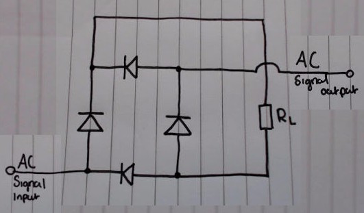
AC signal output is most commonly just connect to ground (0v).

RL represents the circuit to which you’re applying the DC voltage.


Signal diagram explanation

dAC

This shows one full oscillation of the AC signal at the input. Whilst the signal is above the horizontal line, the voltage at the signal input is positive. Whilst the signal is below the horizontal line, the signal input is positive


Flow of current during positive half of the oscillation.

dACp

During the section labelled ‘Input is positive’, here’s how the current flows around the circuit:

dbp

The reason why the current can’t flow through D4, after passing through RL, is because D4 has already been reverse biased by current flowing from the AC input.


Flow of current during negative half of the oscillation.

dACn

During the section labelled ‘Input is negative’, here’s how the current flows around the circuit:

dbn


Conclusion.

As you can see, regardless of whether the AC input is positive or negative, the current flowing through RL never changes. If we could see what the current looked like at RL, It’d look something like this:

dCRL


Notes for future.

I’ll add in a diagram and explanation as to how to dampen the rippling effect seen in the graph above.

Advertisement

LEDs

Light Emitting Diodes (LEDs) are semiconductors that emit light when a current is applied to them. They are comparatively much more energy efficient, when compared to lighting alternatives (E.g filament bulbs), but are generally considerably more expensive.

As with any other didode, LEDs have an anode and a cathode. However, the reverse breakdown voltage is much lower. In addition to this, a resistor is needed in series, in order to limit the rate at which current flows through the LED.

led (1)

Persistance of vision applications – LED matrix

In two dimensional grids of LEDs,  wiring can become excessive and complex. If two wires were to be attached to each LED, it would soon become unmanageable. However, with the use of multiplexing in an LED matrix, the problem is significantly reduced. Instead or there being two connections for every LED, there can instead only have to be one connection for every row, and one connection for every column. In a 8×8 grid this reduces the number of connections from 128, to 16.

led matrix

Multiplexing can be achieved by attaching the anodes of all of the adjacent LEDs in each row together, and attaching the cathodes of all of the adjacent LEDs in each column together. Once this has been done, a specific LED can be turned on by allowing current to flow in through the LEDs row and out through its column.

In practice, each row applies a current sequentially (one after each other) so fast that it is indisguishable by the human eye. Whilst each row is tuned on, the LEDs which are to be turned on allow current to flow out through their individual column. Because of the persistence of vision every row appears to be turned on at the same time.

Multiplexing LEDs

RGB LEDs

RGB LEDs consist of three LEDs (Red, Green, and Blue). They’re all self-contained within the same plastic casing and share either a common anode, or a common cathode.

RGB LED (Common cathode)

Due to the differences in electrical characteristics, a larger resistor is needed in series with the red than that of the green and blue.

Approximate values of: 150Ω, 100Ω, 100Ω are suitable with a 5 volt supply.

Diodes

Overview

A diode is a semiconductor which has two terminals: an anode and a cathode. They are composed of two layers of semiconducting material, one side doped to make it an N-type semiconductor, and the other doped to make it a P-type semiconductor. The anode is on the side of the P-type, and the cathode is on the side of the N-type.(More information about types of semiconductors can be found here: ‘https://tphelectronics.com/2016/09/30/semiconductors/‘).

One of the main characteristics of diodes is that they only allow current to flow in one direction. This means that they can be used to filter out alternating current, or even rectify it with the use of a diode bridge.


Configurations

They’re used both in forward bias, and reverse bias. This refers to the direction in which current flows (forward being anode to cathode, and reverse being cathode to anode).

When forward biased no current flows through the diode until more than the minimum voltage is applied (This is because of the depletion region). This means that it can be used to filter out voltages below this value (e.g noise). The value itself is dependent on the type of diode.

When reverse biased only a few nanoamps flow through the diode.However, If the voltage applied is too large, it’ll cause the diode to breakdown. In most cases this will destroy the diode, but the breakdown in zener diodes do not destroy it (this is used to regulate voltage).

diode-diagram-label