Exclusive OR (XOR) gates operate on the same logic as an OR gate excluding one difference. If more than one of the inputs is true, then the output will be false.
In order for the output to be true, only one of the inputs can be true.


Exclusive OR (XOR) gates operate on the same logic as an OR gate excluding one difference. If more than one of the inputs is true, then the output will be false.
In order for the output to be true, only one of the inputs can be true.

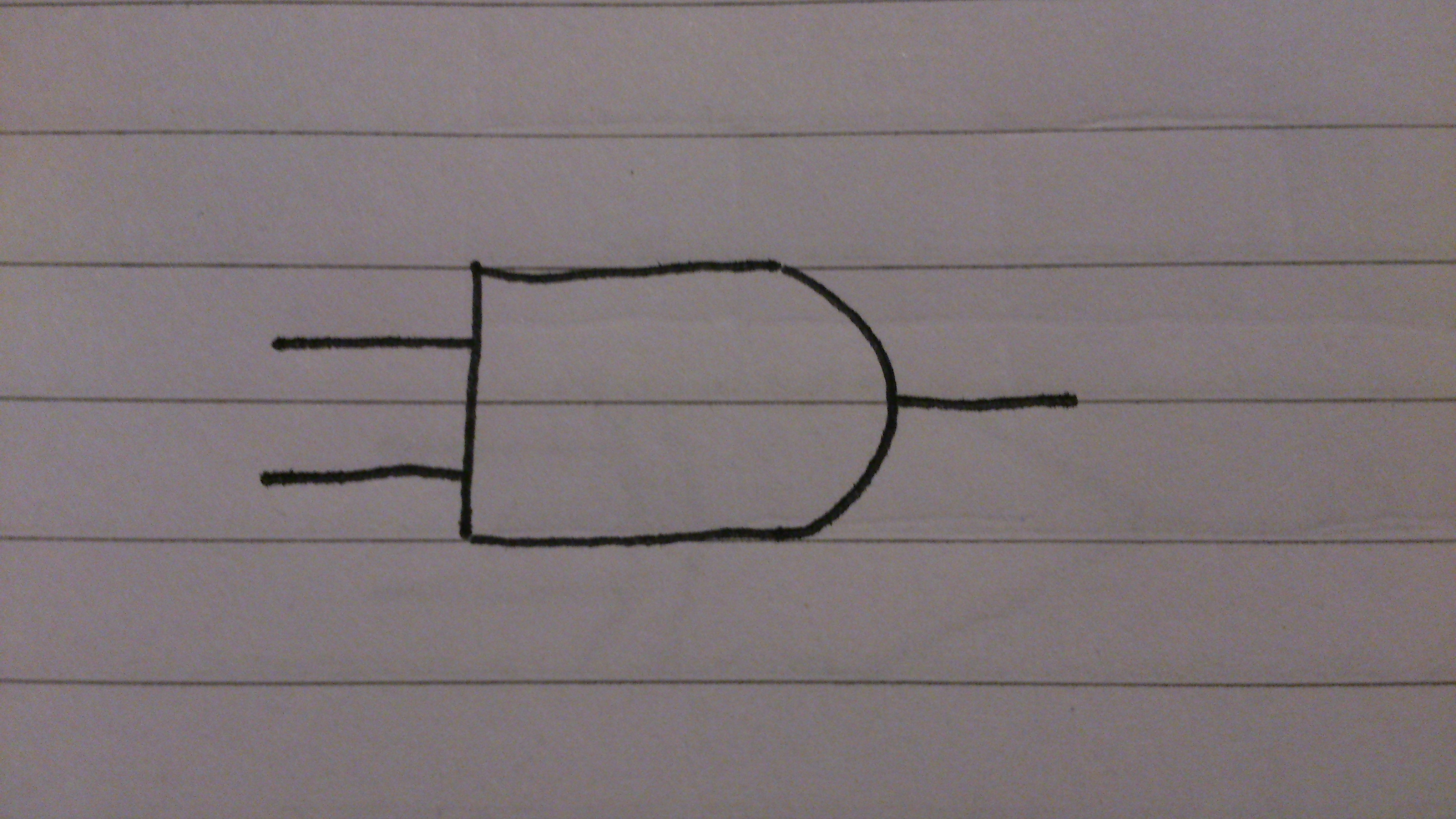
A NAND gate is an AND gate whose output has been inverted. This effectively means that unless all inputs are true, the output will be true.

A NOT gate (Inverter), is a single input logic gate. The output is simply opposite to that of the input.


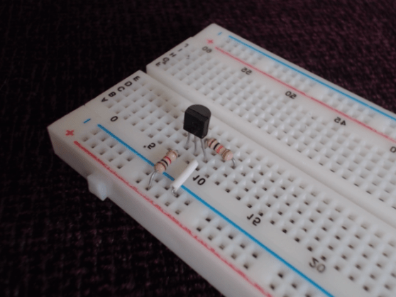
You can simply create a NOT gate by using an NPN transistor and two resistors as shown here: ‘https://thelectronicsblog.wordpress.com/2015/11/29/not-gate-using-a-transistor’


An OR gate only requires one inputs to be true for the output to be true. All inputs need to be false for the output to be false.


An AND gate requires all inputs to be true for the output to be true. Any other combination results in the output being false.
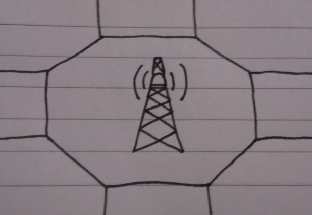
Cellular refers to the structure of the network that phone uses. With cellular phone being the North American term for a mobile phone.
Cellular networks are broken up into cells, these cells are defined by base stations and the distance to which they propagate coverage. In them, radio waves are used instead of physical connections to transmit incoming and outgoing signals. Each base station is allocated a band within the Ultra High Frequency (UHF) portion of the radio frequency spectrum. Adjacent cells must not use the same transmission frequencies, as their areas of propagation overlap, and would cause interference. However, Non-adjacent cells are far enough away for their to be no overlap and frequency re-use is feasible.
Each base station has a limited number of uplink and downlink frequencies, to allocate to phones connecting to the network (making a call). However, because only a comparatively small amount of people are ever connected to a call at any one time, this limit is rarely every reached. An example of when an instance of this has occurred would 7/7 London Bombings, where a large part of the O2 network in London was shut down to everyone (excluding members of emergency services), so as to prevent the system from overloading and crashing calls.
For the 2012 London Olympics, pre-emptive measures were taken to ensure that the network could accommodate the increased number of uses that would be using it. Additional base stations were set-up temporarily around the area at which the Olympic grounds were.
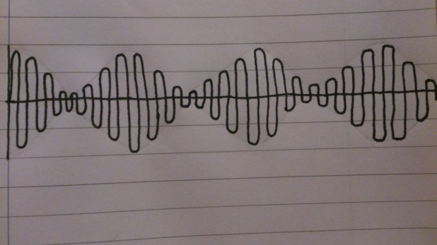
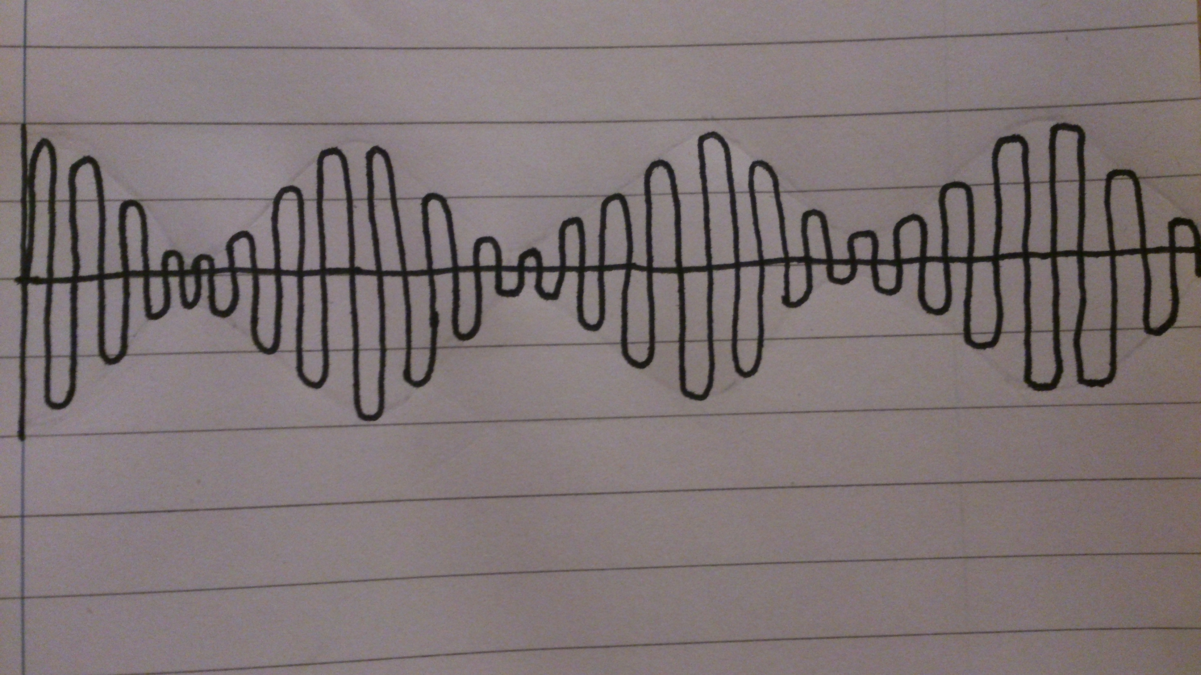
Modulation refers to the modification of a carrier wave to accommodate a signal. In Amplitude Modulation (AM), the carrier wave has its amplitude varied in correspondence with the signal. In Frequency Modulation (FM), the carrier wave has its frequency varied in correspondence with the signal.


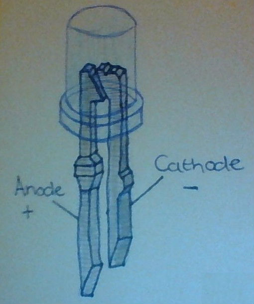
Light Emitting Diodes (LEDs) are semiconductors that emit light when a current is applied to them. They are comparatively much more energy efficient, when compared to lighting alternatives (E.g filament bulbs), but are generally considerably more expensive.
As with any other didode, LEDs have an anode and a cathode. However, the reverse breakdown voltage is much lower. In addition to this, a resistor is needed in series, in order to limit the rate at which current flows through the LED.

In two dimensional grids of LEDs, wiring can become excessive and complex. If two wires were to be attached to each LED, it would soon become unmanageable. However, with the use of multiplexing in an LED matrix, the problem is significantly reduced. Instead or there being two connections for every LED, there can instead only have to be one connection for every row, and one connection for every column. In a 8×8 grid this reduces the number of connections from 128, to 16.
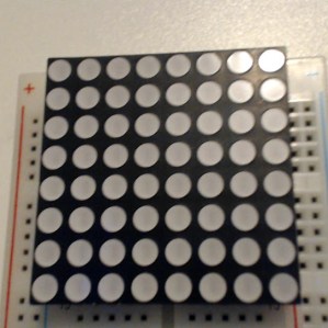
Multiplexing can be achieved by attaching the anodes of all of the adjacent LEDs in each row together, and attaching the cathodes of all of the adjacent LEDs in each column together. Once this has been done, a specific LED can be turned on by allowing current to flow in through the LEDs row and out through its column.
In practice, each row applies a current sequentially (one after each other) so fast that it is indisguishable by the human eye. Whilst each row is tuned on, the LEDs which are to be turned on allow current to flow out through their individual column. Because of the persistence of vision every row appears to be turned on at the same time.

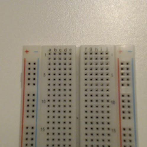
Breadboard is used to prototype new circuits. It consists of a plastic housing with holes used to thread wire/components into. the holes are connected in lines by conductive material to adjacent holes. The diagram below shows which holes are connected to each other and how a breadboard is generally laid out (the green lines represent the conductive material).


