LEDs

Light Emitting Diodes (LEDs) are semiconductors that emit light when a current is applied to them. They are comparatively much more energy efficient, when compared to lighting alternatives (E.g filament bulbs), but are generally considerably more expensive.

As with any other didode, LEDs have an anode and a cathode. However, the reverse breakdown voltage is much lower. In addition to this, a resistor is needed in series, in order to limit the rate at which current flows through the LED.

led (1)

Persistance of vision applications – LED matrix

In two dimensional grids of LEDs,  wiring can become excessive and complex. If two wires were to be attached to each LED, it would soon become unmanageable. However, with the use of multiplexing in an LED matrix, the problem is significantly reduced. Instead or there being two connections for every LED, there can instead only have to be one connection for every row, and one connection for every column. In a 8×8 grid this reduces the number of connections from 128, to 16.

led matrix

Multiplexing can be achieved by attaching the anodes of all of the adjacent LEDs in each row together, and attaching the cathodes of all of the adjacent LEDs in each column together. Once this has been done, a specific LED can be turned on by allowing current to flow in through the LEDs row and out through its column.

In practice, each row applies a current sequentially (one after each other) so fast that it is indisguishable by the human eye. Whilst each row is tuned on, the LEDs which are to be turned on allow current to flow out through their individual column. Because of the persistence of vision every row appears to be turned on at the same time.

Multiplexing LEDs

Breadboard

Breadboard is used to prototype new circuits. It consists of a plastic housing with holes used to thread wire/components into. the holes are connected in lines by conductive material to adjacent holes. The diagram below shows which holes are connected to each other and how a breadboard is generally laid out (the green lines represent the conductive material).

breadboard

breadboarsrsrs

Persistence of vision

The human eye retains an image for a short while after the actual image has been removed.

If the oscillations of a light turning on and off, are faster than which the human eye can detect change, the light appears to be permanently turned on.

The duty-cycle refers to the period of time that the light is turned on. If a light is on for half of the time, the duty cycle would be 50%. In this case, if the oscillations are fast enough, the light will appear to be on for the full duration of the on off cycle, but at half of the actual brightness of when it’s turned on.

pwm

Decoupling Capacitors

Capacitors block DC whilst allowing AC through. If there is noise present on a DC voltage, a capacitor can link the circuit directly to ground. The effect of this is that any noise (as AC) will filter down through the capacitor to ground, whilst DC will pass though the rest of the circuit as though the capacitor wasn’t there. When used in this way it is known as a decoupling capacitor.

coupling capacitor

Operational Amplifiers

Op Amps (Operational Amplifiers) are composed of two inputs, an output, and positive and negative power supply pins.

Op Amps can be used in many different set-ups, among them being: Voltage Comparators, Inverting and Non-inverting amplifiers, Summing amplifiers, and Difference amplifiers.

In Op Amps, the voltage of the output is dependent on the voltages of the two inputs. If the Inverting input is higher, the output will be the same as the negative supply. If the Non-Inverting input is higher, the output will be the same as the positive supply.

Pins 2, 3, 4, 6, and 7 are the only pins which need to be connected to the circuit in order to use the Op Amp.

LM741 Operational Amplifier actual viewop amp schematic

RGB LEDs

RGB LEDs consist of three LEDs (Red, Green, and Blue). They’re all self-contained within the same plastic casing and share either a common anode, or a common cathode.

RGB LED (Common cathode)

Due to the differences in electrical characteristics, a larger resistor is needed in series with the red than that of the green and blue.

Approximate values of: 150Ω, 100Ω, 100Ω are suitable with a 5 volt supply.

The Basics – Volts and Amps

All circuits require an electric current to work, this is the flow of electrically charged particles. The rate at which current flows through a circuit is measured in amps.

In order for current to flow, there needs to be a potential difference between two points. This is measured in volts. If the positive terminal of a battery is 5v and the negative terminal is 0v, the potential difference is 5v. As long as the potential difference is above 0, current will flow.

basics

Diodes

Overview

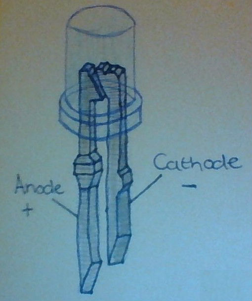
A diode is a semiconductor which has two terminals: an anode and a cathode. They are composed of two layers of semiconducting material, one side doped to make it an N-type semiconductor, and the other doped to make it a P-type semiconductor. The anode is on the side of the P-type, and the cathode is on the side of the N-type.(More information about types of semiconductors can be found here: ‘https://tphelectronics.com/2016/09/30/semiconductors/‘).

One of the main characteristics of diodes is that they only allow current to flow in one direction. This means that they can be used to filter out alternating current, or even rectify it with the use of a diode bridge.


Configurations

They’re used both in forward bias, and reverse bias. This refers to the direction in which current flows (forward being anode to cathode, and reverse being cathode to anode).

When forward biased no current flows through the diode until more than the minimum voltage is applied (This is because of the depletion region). This means that it can be used to filter out voltages below this value (e.g noise). The value itself is dependent on the type of diode.

When reverse biased only a few nanoamps flow through the diode.However, If the voltage applied is too large, it’ll cause the diode to breakdown. In most cases this will destroy the diode, but the breakdown in zener diodes do not destroy it (this is used to regulate voltage).

diode-diagram-label